Introduction of brain computer interface to neurologists
Article information

Abstract
A brain-computer interface (BCI) is a technology that acquires and analyzes electrical signals from the brain to control external devices. BCI technologies can generally be used to control a computer cursor, limb orthosis, or word processing. This technology can also be used as a neurological rehabilitation tool for people with poor motor control. We reviewed historical attempts and methods toward predicting arm movements using brain waves. In addition, representative studies of minimally invasive and noninvasive BCI were summarized.
INTRODUCTION
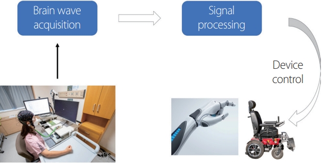
Hans Berger first succeeded in measuring electrical signals generated in the human brain from the scalp in 1924 using an electroencephalogram (EEG), which provided useful information for clinical practice such as determining convulsions, sleep, and brain death. Some scientists have considered EEGs to be helpful for people who were physically disabled by controlling a computer or machine through appropriate signal processing (Fig. 1). These ideas have now been developed and supported by studies, and implemented as a brain-computer interface (BCI), brain-machine interface (BMI), neural control interface, mind-machine interface, and direct neural interface, with BCI and BMI being the most common.
Jacques Vidal introduced the name BCI. In a paper published in 1973, he defined BCI based on the ability to manipulate objects through brain waves.1 BMI was developed by a group of neurophysiologists who suspected that the imprecision of noninvasive EEG signals only made them useful for selecting from among a small number of options. They suggested that collecting electrical signals directly from the brain through invasive methods would allow the more-accurate control of external machines, which was a technique they named BMI.2 The recent developments of BCI and BMI have resulted in them being used interchangeably, and BMI can also be called intracortical BCI (iBCI).3
This article reviews the history and principles of iBCI research with a focus on research that predicts arm movements by analyzing the electrical activity in the brain, and minimally invasive and noninvasive BCI research that has attempted to overcome the limitations of iBCI. We aimed to explain these in a manner that would be easy for neurologists to understand.
HISTORY AND PRINCIPLES OF ARM-MOVEMENT PREDICTION
Initial study
Attempts to analyze movements by deciphering electrical signals in the cerebral cortex of monkeys began in the 1960s. Evarts conducted experiments using monkeys trained to receive fruit juice as a reward for performing wrist flexion and extension.4 Of the pyramidal tract neurons in the precentral gyrus of monkeys, 31 were identified as being involved in wrist movement, and the spike frequency (firing rate) of the neurons increased or decreased when flexion and extension were performed. Spike frequency was also indicated to increase when loads exerted forces during the movements.
Humphrey et al.5 subsequently conducted experiments on monkeys using the same methodology as Evarts, and measured the spike frequency (firing rates) of pyramidal tract neurons in the precentral gyrus during flexion and extension. Humphrey et al.5 aimed to predict wrist position by entering their data into the following equation:
where t is the time, Φ(t) is the wrist position at that time, and Ui (t) is the spike frequency at the ith unit. When performing flexion and extension, the spike frequency and wrist position information were repeatedly measured at certain time increments and entered into the above formula to obtain the constants a0 and ai. This indicated that arm position can be inferred from the spike frequency alone.
Direction prediction in two dimensions
The most impressive study on predicting the arm movements of monkeys by analyzing electrical activity generated in the cerebral cortex was reported by Georgopoulos et al.6 in 1982. Their experiment used a monkey that was trained to move its arm in the direction of table sections randomly lit by nine light emitting diodes (LEDs) (0, 45, 90, 135, 180, 225, 270, and 315 degrees, and center). When the neurons in the motor cortex area of the monkey responsible for arm movements were measured, certain neurons exhibit increased spike frequencies when the arm was moved in a specific direction, which decreased when moving in the opposite direction (Fig. 2). Georgopoulos et al.6 measured the spike frequency of a particular neuron as the arm moved in each direction, and tried to determine the preferred movement direction for the neuron using a set of formulas. The first was
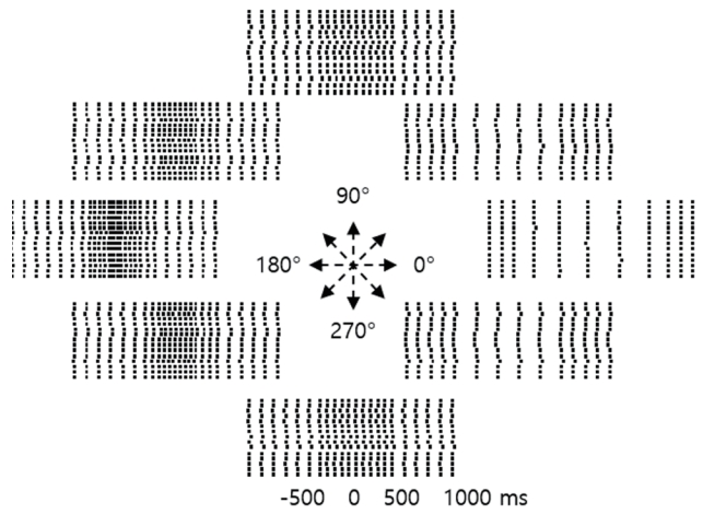
Direction predictions based on neuron firing rates. Impulse activity was recorded from a single neuron during repeated arm movements toward the target. Neurons fire just (about 300 ms) before the onset of movement (i.e., 0 ms). Each dot represents a neuron firing, and each row on the vertical axis represents a repetitive arm movement in the same direction. Firing rates increased when the arm was moved 180 degrees in the desired direction and decreased when the arm was moved back to 0 degrees, suggesting that the recorded neuron prefers to move the arm toward 180 degrees.
where yi (i = 1,2, 3, ..., 8) is the average spike frequency that occurs when moving in the θi direction (θi = 0, 45, 90, …, 315 degrees). Repeatedly entering the average spike frequencies measured in each direction will yield the values of constants b0, b1, and b2. The following formula can infer the spike frequency of neurons when moving in each direction:
This formula can be converted to
where θ0 is the preferred direction and b0, b1, and b2 are the regression coefficients. This formula can be used to produce a plot with the angle at which the LED is lit on the x-axis and the spike frequency on the y-axis. The angle corresponding to the vertex of this graph is the direction in which the neuron prefers to move the arm of the monkey.
Direction prediction in three dimensions, and artificial intelligence
Georgopoulos et al.7 repeated the same experiment in a three-dimensional cube environment rather than a two-dimensional plane, since neurons with directionality exist in a three-dimensional environment, and found that the direction in which the neurons prefer to move the arm can be determine. They subsequently demonstrated that it is possible to calculate the direction of the neuronal population using a formula that gives weight if the spike frequency is high during an analysis, by also collecting data from adjacent neurons.8
With the recent development of artificial intelligence technology, the flexion and extension of the hand of a monkey can be predicted after only 5-10 minutes of training.9 A previous study indicated that it is possible to distinguish the direction by analyzing the local field potential instead of just the measured spike.10
HISTORY OF THE IBCI
Animal study
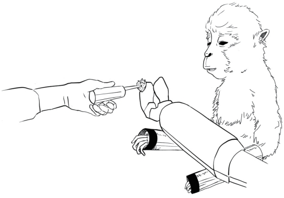
The most successful study on iBCI using monkeys was reported in 2008 by Velliste and colleagues, including Andrew Schwartz who had worked with Georgopoulos. They successfully moved a robotic arm in a three-dimensional space using the brain wave signals of a monkey.11 Electrical signals from the brain were first obtained by inserting intracortical microelectrode arrays into the primary motor cortex area of the monkey. They then identified channels that were preferentially involved during movements along the x-axis, y-axis, and z-axis in a three-dimensional space. By calculating the spike frequency in the corresponding channel, they attempted to move the robotic arm in a three-dimensional space to the target point so that the monkeys could eat food by bringing it to the mouth (Fig. 3). Two monkeys were included in the study, with accuracies of 67% and 78%.
Human study
The successful experiments on monkeys led to experiments involving humans. The first study to be performed on humans included two patients who had been quadriplegic for several years due to a brain stem infarction.12 Microelectrode arrays with 96 channels were inserted into the motor cortex hand areas of the dominant hemisphere of these patients. Similarly to the monkey experiment, the channels that preferentially moved the arm forward, backward, left and right, and up and down, and those that preferentially clenched and released the fist were identified, and the robotic arm could then be moved based on this analysis.
Another study was conducted on patients with spinocerebellar degeneration.13 In that study, two intracortical microelectrode arrays were inserted under the guidance of magnetic resonance imaging and functional magnetic resonance imaging. Unlike in the abovementioned study, the robotic arm could also be moved clockwise and counterclockwise in addition to clenching and releasing the fist by moving forward, backward, left and right, and up and down.
Beyond a single robotic arm
Another subsequent study was performed on a patient who developed quadriplegia from a cervical spine cord injury caused by a traffic collision.14 A microelectrode array was inserted into the left cerebral hemisphere hand area of the subject, and the subject wore a neuromuscular electrical stimulation sleeve on their right arm that moved their arm, instead of a robotic arm, so that the four movements of wrist flexion, wrist extension, and radial and ulnar deviation of the wrist were possible.
Studies on transmitting sensory information to the brain through a robotic arm have also been conducted.15 Two microelectrode arrays (with 88 channels) were inserted into the motor cortex hand and arm regions of patients with a cervical-spine cord injuries, and two microelectrode arrays (with 32 channels) were inserted into the hand and arm cutaneous regions of the somatosensory cortex. Torque measurements of the robotic arm were set to transmit the stimulus to the electrodes inserted into the somatosensory cortex, and a robotic arm moved and grabbed the target object. A comparison between the time to move and grab the target object was performed when the sensory stimulus was either delivered or not delivered, which indicated that providing sensory information shortened the required time.
MINIMALLY INVASIVE BCI
The technique of inserting microelectrodes into the brain carries significant risks, including causing infection or seizures. In addition, the signal measurement sensitivity of the electrode decreased with time.16 A proposed minimally invasive method as an efficient and safer option is currently being studied.
Stentrode
Studies have been conducted using a Stentrode (a stent device attached to electrodes that is capable of measuring electrical signals from the brain) with the help of intracranial endovascular management (Fig. 4A). An animal experiment was initially conducted. In this experiment, electrical activities of the brain were obtained by inserting a Stentrode into the superior sagittal sinus. Comparing the quality of the electrical activities collected from the brain indicated that the bandwidths of those collected through invasive methods (classic electrodes implant in subdural space and epidural space) were not as good as those collected through subdural electrodes, but were similar to those collected through epidural electrodes. However, the power obtained was indicated to be similar to that for the subdural electrode.17

Minimally invasive devices. (A) Stentrode with 8 × 750 μm electrode discs self-expanding during administration by a 4F catheter. Scale bar, 3 mm. The device is usually implanted in the superior sagittal sinus to obtain the electrical activity of the brain. Figure adapted from Oxley et al.17 (B) Neural threads. “Tree” probes with electrode contacts spaced by 75 μm. Scale bar, 100 μm. Figure adapted from Musk.19
A subsequent experiment was conducted on amyotrophic lateral sclerosis (ALS) patients. In that study, the cursor of a computer mouse was moved by pupil movement, and left clicking or zooming was performed based on information obtained from the Stentrode.18 However, the Stentrode did not appear to be permanently usable, and its applications may be restricted by certain risks.
Neuralink
Meanwhile, Elon Musk has also been interested in a minimally invasive BCI, and has conducted several studies on the subject. Musk19 founded a company called Neuralink, developed small and flexible electrode “threads” (with up to 3,072 electrodes per array distributed across 96 neural threads), and conducted animal experiments (Fig. 4B). When conducting experiments on mice in 2019, the Link tool that covers neural “threads” and transmits EEG information was inserted under the skin. In 2020, Link was successfully upgraded to wirelessly transmit the EEG information of pigs through neural threads. In 2021, it was announced on YouTube that Neuralink succeeded in playing the “mindpong” game with neural activity by inserting a device into the monkey. However, the findings of these studies need further verification.
NONINVASIVE BCI
Since the majority of noninvasive BCI applications use scalp EEGs, the information obtained from brain signals is minimal, and sophisticated movements such as arm movements cannot be implemented in the above-mentioned iBCI and minimally invasive BCI studies. However, compared with invasive methods, several noninvasive BCI-based methods have been devised for quadriplegic patients due to their minimal risk, and have the advantage of being able to permanently retain brain waves.
Visual evoked potentials
The first study on noninvasive BCIs was attempted by Vidal. The experiment was performed by moving a cursor on a computer screen using visual evoked potentials (VEPs) to escape a maze.20 However, it was limited by a lack of precision.
Slow cortical potentials
When concentration or movement occurs, EEG potentials change after 0.5-10 seconds, which is called slow cortical potentials (SCPs). Increases and decreases in cerebral activity can be observed as negative and positive SCPs, respectively.21 Using the SCP phenomenon, ALS patients succeeded in delivering a message by selecting letters by moving the cursor on the computer screen.22 However, the signal appears slowly and an accurate distinction is not made, which restricts applications of this technique.
Event-related desynchronization and synchronization
Waveforms at 8-12 Hz observed in the motor cortex area of the cerebrum are called mu rhythms, and are known to be related to movement. Decreases in mu and beta rhythms are observed in the motor cortex area during movement preparation and execution phases, which is called event-related desynchronization (ERD).23 Increases in mu and beta rhythms are observed in the motor cortex area before movement ceases, which is called event-related synchronization (ERS). However, BCI research using ERD and ERS has been restricted by their low recognition rates.
P300 wave
Applying a stimulus induces a positive peak in the parietal lobe that appears about 300 ms later, which is called P300 and is used in noninvasive BCI. The most representative method involves using a 6 × 6 screen containing letters and several word commands.24 If the subject continues to look at the desired letter while the lights in the rows and columns flash randomly, a P300 wave occurs when the lights of the desired letter are turned on. Using this method, the text input of the subject is a noninvasive BCI using the P300 VEP. This method has been established as the most basic BCI method utilizing P300 for applications in future studies, but it has the disadvantages of needing visual stimulation and continuous flashes of light.
Steady-state VEP
Noninvasive BCI also includes methods based on steadystate VEPs.25 This method utilizes a phenomenon in which the intensities at certain frequencies in the occipital lobe increase in proportion to the visual stimulus frequencies. For example, a visual stimulus blinking at 7 Hz is proportionally measured at 7 Hz by the EEG on the occipital lobe, which may be identified by neurologists as “photic stimulation” during an EEG examination. Although its relatively good recognition rate is an advantage, it also has the disadvantage of requiring visual stimulation and inconvenience from continuously seeing the blinking objects. It may also cause headaches or convulsions in some cases.
CONCLUSION
This article has introduced and explained the history of brain wave acquisition and processing during arm movements, adaptation to iBCI, and various minimally invasive BCI and noninvasive BCI applications in a way that neurologists can easily understand. iBCI has the advantage of predicting arm movements and being able to make precise movements, but it can cause infection or seizures, and is difficult to use permanently due to the signal measurement sensitivity of the electrode decreasing over time.16 While BCI is minimally invasive compared to iBCI, it lacks precision, and the signal measurement sensitivity of the electrode decreases over time.17 The noninvasive method is safer and is capable of continuously receiving EEG signals, but it has difficulty in implementing precise movements such as in the arm, and it therefore remains restricted to selecting from among only several options. It also often has a poor recognition rate or needs additional stimuli such as flashlights.
Each method has several advantages and disadvantages, and so none can be concluded as being better than the others. However, since these technologies can help quadriplegic patients suffering from conditions such as ALS, brain stem stroke, and cervical spine cord injury to manipulate the external world as they desire, interest in these techniques might particularly come from neurologists who directly interact with them. Since the currently developed technology is difficult to implement outside the laboratory due to its high cost, a cost-effective implementation strategy is needed to enable practical applications that are helpful in daily life.
Notes
Conflicts of Interest
The authors have no conflicts to disclose.